
The std_logic_vector type can be used for creating signal buses in VHDL. The std_logic is the most commonly used type in VHDL, and the std_logic_vector is the array version of it.
While the std_logic is great for modeling the value that can be carried by a single wire, it’s not very practical for implementing collections of wires going to or from components. The std_logic_vector is a composite type, which means that it’s a collection of subelements. Signals or variables of the std_logic_vector type can contain an arbitrary number of std_logic elements.
This blog post is part of the Basic VHDL Tutorials series.
The syntax for declaring std_logic_vector signals is:
signal <name> : std_logic_vector(<lsb> to <msb>) := <initial_value>;
or
signal <name> : std_logic_vector(<msb> downto <lsb>) := <initial_value>;
where <name> is an arbitrary name for the signal and <initial_value> is an optional initial value. The <lsb> is the index of the least significant bit, and <msb> is the index of the most significant bit.
The to or downto specifies the direction of the range of the bus, basically its endianess. Although both work equally well, it’s most common for VHDL designer to declare vectors using downto. Therefore, I recommend that you always use downto when you declaring bit vectors to avoid confusion.
The VHDL code for declaring a vector signal that can hold a byte:
signal MySlv : std_logic_vector(7 downto 0);
The VHDL code for declaring a vector signal that can hold one bit:
signal MySlv : std_logic_vector(0 downto 0);
The VHDL code for declaring a vector signal that can hold zero bits (an empty range):
signal MySlv : std_logic_vector(-1 downto 0);
library ieee;
use ieee.std_logic_1164.all;
entity T11_StdLogicVectorTb is
end entity;
architecture sim of T11_StdLogicVectorTb is
signal Slv1 : std_logic_vector(7 downto 0);
signal Slv2 : std_logic_vector(7 downto 0) := (others => '0');
signal Slv3 : std_logic_vector(7 downto 0) := (others => '1');
signal Slv4 : std_logic_vector(7 downto 0) := x"AA";
signal Slv5 : std_logic_vector(0 to 7) := "10101010";
signal Slv6 : std_logic_vector(7 downto 0) := "00000001";
begin
-- Shift register
process is
begin
wait for 10 ns;
for i in Slv6'left downto Slv6'right + 1 loop
Slv6(i) <= Slv6(i-1);
end loop;
Slv6(Slv6'right) <= Slv6(Slv6'left);
end process;
end architecture;
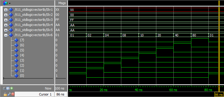
In this exercise we declared six std_logic_vector buses, each eight bits long (one byte).
Signal Slv1 was declared without a initial value. The bus is seen having the value XX in the waveform screenshot. This is because the value that is displayed on the bus is in hexadecimals, and XX indicates a non-hex value. But when we expanded the bus in the waveform, we could see that the individual bits were indeed U’s.
Signal Slv2 was declared using an initial value of all 0’s. Instead of specifying the exact value for each bit, we used (other => '0') in place of the initial value. This is known as an aggregate assignment. The important part is that it will set all bits in the vector to whatever you specify, no matter how long it is.
Signal Slv3 was declared using an aggregate assignment to give all bits the initial value of 1. We can see FF displayed on this signal in the waveform, which is hex for eight 1’s.
Signal Slv4 was declared with an initial value specified in hex, AA. Each hex digit is 4 bits long, therefore we must supply two digits (AA) for our vector which is 8 bits long.
Signal Slv5 declares exactly the same initial value as Slv4, but now we specified it as the binary value 10101010. We can see from the waveform that both signals have the hex value AA.
Signal Slv6 was declared with an initial value of all zeros, except for the rightmost bit which was '1'. We used a process to create a shift register from this signal. The shift register, as the name implies, shifts the contents of the vector one place to the left every 10 nanoseconds.
Our process wakes up every 10 ns, and the For-Loop shifts all bits in the vector one place to the left. The final bit is shifted back into the first index by the Slv6(Slv6'right) <= Slv6(Slv6'left); statement. In the waveform we can see the '1' ripple through the vector.
This is a visualization of how the '1' propagates through our shift register:

By using the 'left' and 'right attributes, we made our code more generic. If we change the width of Sig6, the process will still work. It’s good design practice to use attributes where you can instead of hardcoding values.
You may be wondering if there are more attributes that you can use, and there are. I won’t be talking more about them in this tutorial series, because I consider them to be advanced VHDL features.
N-bit vectors should be declared using std_logic_vector(N-1 downto 0)
A vector can be assigned as a whole or bits within it can be accessed individually
All bits in a vector can be zeroed by using the aggregate assignment (others => '0')
Code can be made more generic by using attributes like 'left and 'right
از attribute برای تغییر پارامتر ها در کد استفاده میشود.
ارزش بیت ها در کد متفاوت است MSB و LSB


درباره این سایت